
Homemade Hardware - Week 2
ATtiny85 jig and capacitive sensing
After securing tools for the class and doing our first bit of surface mount soldering with a heatgun in the first week, this week’s Homemade Hardware homework saw us tasked with (1) making a programming jig for an ATtiny85 and (2) breadboarding an example of multiple LEDs controlled via capacitive sensors using this library.
The jig
Following the example here but adapted for an Arduino Nano 33 IoT, creating this programming jig was pretty straightforward conceptually but physically tricky.
The Nano 33 is tiny! So was the bit of perf board used for the jig, which meant there wasn’t much distance between the pins that needed to be soldered. I did join up one pin from the 8-pin socket to the wrong Arduino pin incorrectly, but that was easy to remedy with some desoldering wick.
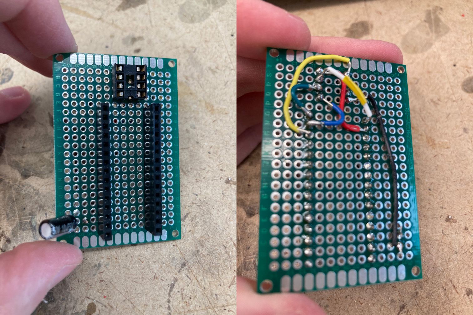
This jig is not pretty–note the little bit of electrical tape on the white wire between the socket pin #7 for the ATtiny85’s SCK pin and the digital #12 pin of the Nano, which is there since part of the wire’s insulation split while gripping it with tweezers. I did a quick test to confirm it works, though, and since there’s not a lot of give in the wires I imagine this’ll work for as long as I need it to.
Capacitive sensing
Didn’t want to overthink this part. After reading the documentation (this PJRC page was particularly handy) I grabbed some resistors (one 10M ohm, one 510k ohm, two 4.7k ohm, two 220 ohm) out of the shop parts bin, some wire, and split two pieces of copper clad board off of a left behind scrap piece.
My plan was to make two sensors, one that turned an LED only while being touched, and one that would activate once your hand/finger was hovering close to the copper surface. Per the documentation I read, a 10M ohm resistor used for the “send” pin would create the latter behavior, and 510k ohm was toward the lower end of what was recommended for touch-only activation.
Again, not the most beautiful soldering job here. I also attached some wires to the send and receive resistors just to make it easier to access the copper pads. At first I connected up the pads according to the capacitive sensor library’s example code to get a sense for how they work.
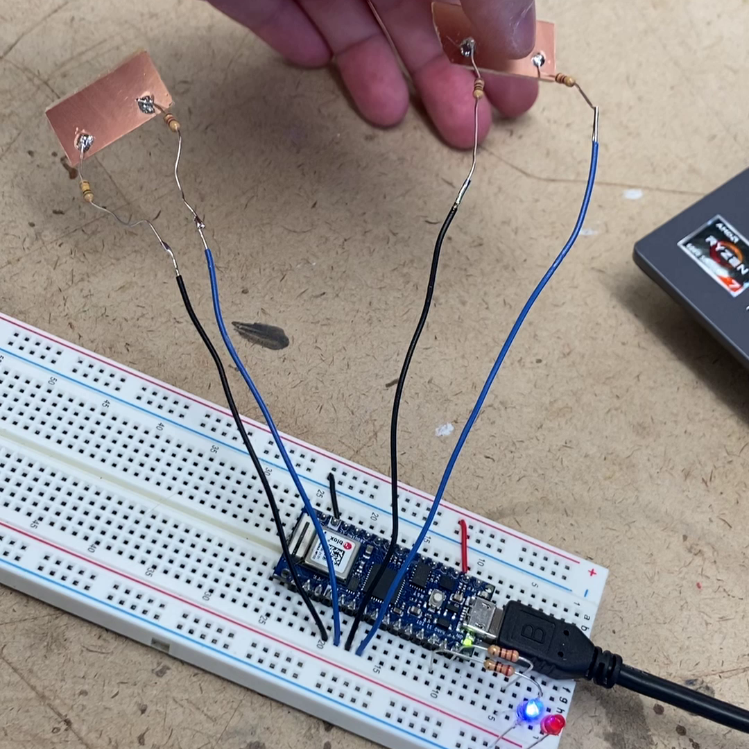
Link to short video of breadboarded project on YouTube
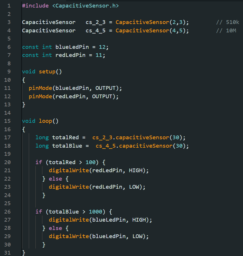
The pad with the 510k ohm send was pretty well behaved: it returned readings between 0 and 20 at rest, and around 5,000 or so when touched. I had to troubleshoot the other pad–think I had a bad connection to one pin at first–and then could see it giving readings of around ~250 at rest and between 400,000 and 600,000 when fully touched. I could see those readings ramp up as I held my finger closer. My ultimate choice of a threshold at 1,000 was arbitrary, I’m sure with more testing you could dial in a threshold for a more precise distance from the pad.
The sketch I wrote is basically just a mashup of the capacitive sensing example and the included Arduino button control example. Nothing fancy!
–2/5/23