
Physical Computing - 10/12/22
Midterm madness
After two weeks filled with a lot of trial and error, a little frustration, and a couple breakthroughs, I’ve finished this spooky project: a Halloween decoration disguised as a suspiciously deep mirror.
[Link to demonstration video on YouTube here]
It doesn’t really have a name. I could call try to call it something deep, like “Mirror for the Soul.” Or maybe “Bone Machine?”
The end result is fairly close to the idea I originally sketched and presented a few weeks ago in class. That day I ordered a strip of NeoPixels (one meter with 30 LEDs, black PCB) and a 12V wall wart from Adafruit.
I encountered my first hurdle in creating the project when I began working with the NeoPixels. Fearful of accidentally misusing them, I combed through Adafruit’s documentation to be sure I was hooking them up to my Arduino Nano 33 IOT and breadboard correctly. Adafruit recommends using at least a 1,000 microfarad capacitor in tandem with a meter of NeoPixel strip–it actually ended up being a photo featured on the Adafruit store listing for the product that helped me get things oriented correctly. I used a 4,700 microfarad capacitor from the Shop.
Next came time to wrap my head around the VL53L0X time of flight sensor, which first required gaining some more confidence soldering. A professor whose name I didn’t catch actually snatched the sensor away from me when I came to him asking if he could help demonstrate the best practices for soldering such on such a small board. Not ideal! But I made sure to schedule time to go over the same techniques with Yonatan, which I used the kit-included motor driver to learn on. Now that’s correctly soldered to two sets of pin headers as well.
With the NeoPixel and VL53L0X libraries installed and examples working properly with how I hooked everything up, I set out to acquire the rest of what I needed. I don’t have the fabrication skills necessary to build a picture frame from scratch (at least not in the time provided) so I bought a large shadow box for about $30 from Michael’s. The two-way mirror acrylic came from Canal Plastics. With the help of Luke and Yonatan I laser cut the ⅛” thick acrylic sheet to 10.25”x10.25” to replace the glass included with the shadow box.
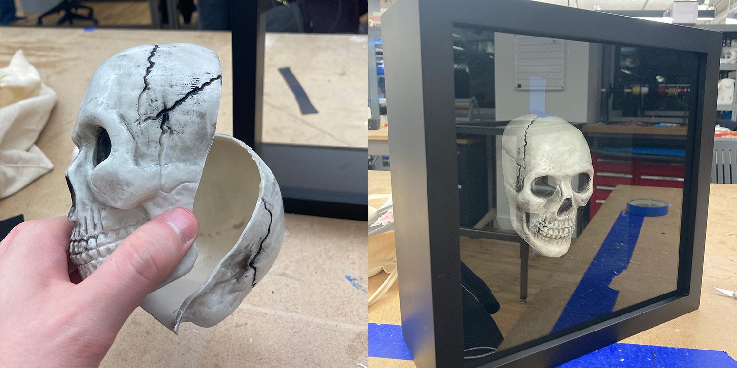
Kay Wasil graciously provided the hollow plastic skull that I ended up using in the project. I used an Xacto knife to slice it in half, following the existing injection mould line. With approixmately four inches of space to work with inside the shadow box, I needed to get the skull down to a size where I’d have adequate clearance between it and the acrylic while also leaving room for the components (Arduino etcetera) hidden behind the mounting board. I ended up removing from spacers nailed into the shadow box, trimmed them by an inch using the Xacto to score and snap the material (I didn’t want to use a bandsaw because there were made of pressboard, not real wood). With those trimmed to size I could move the styrofoam sheet that came with the shadowbox closer to the acrylic, creating an inch wide compartment in the back to hide the components used.
As presented in class, I have the VL53L0X exposed at the front of the shadowbox. This was intentional, though under other circumstances I would have liked to conceal it. My first thought was that it might be able to see through the acrylic, but the laser simply reflects off of the material. I didn’t like the idea of cutting or drilling a hole in the acrylic, and I’m not confident enough in my fabrication skills to create a cavity in the shadowbox that then could have become an integrated shroud disguising the sensor. I made sure to cut and solder wire to the pinheaders of the VL53L0X long enough that I could position it how I please and such that I could have some leeway in repositioning it in case I create a shroud later.
At the end of the day, I do like the look of exposed electronics. I also feel like the sensor being exposed invites people to examine the piece, at which point a viewer will probably get within the range to activate the lights.
The code for the project is fairly simple, and is presented below in a “clean” format with comments and extraneous test code removed.
Credit to the authors of the Adafruit Arduino libraries for NeoPixel products and the VL53L0X sensor (Phil Burgess and Limor Fried) for creation of the examples that formed the basis for this code.
#include <Adafruit_NeoPixel.h>
#include <Adafruit_VL53L0X.h>
#define PIN 6
#define NUMPIXELS 29
int loxState = 8190; //set to "max" range of VL53L0X sensor at startup
Adafruit_NeoPixel strip(NUMPIXELS, PIN, NEO_GRB + NEO_KHZ800);
Adafruit_VL53L0X lox = Adafruit_VL53L0X();
unsigned long previousTime = 0;
const long checkInterval = 500;
//use milliseconds to time sensor checks between NeoPixel animations
void setup() {
strip.begin();
Serial.begin(9600);
lox.startRangeContinuous();
//begin ranging, adapted from VL53L0X Continuous ranging example
}
void loop() {
unsigned long timeNow = millis();
//again, use millis() to avoid delays on delays. Similar model to Blink w/o delay
loxState = lox.readRange();
//set the variable we pass to the NeoPixel based on range
if (timeNow - previousTime >= checkInterval) {
if (loxState > 450) {
strip.clear();
} else {
colorBlast(strip.Color(255, 0, 0), loxState / 3);
}
//if out of range, clear strip, else animate with delay determined by distance
if (loxState < 450) {
colorBlast(strip.Color(0, 0, 0), loxState / 3);
} else {
colorBlast(strip.Color(0, 0, 0), 100);
}
//handle other anim cases to animate clearing of pixels one by one
}
}
//animation pulled from NeoPixel example
for (int i = 0; i < strip.numPixels(); i++) {
strip.setPixelColor(i, color);
strip.show();
delay(wait);
}
}
A major problem I had toward the end of my design process came from over-reliance on existing libraries. I’m sure this has to be a fairly commonplace experience with projects like these–you buy a new component, grab the library to control it, begin iterating based on some example… and bam, you run into an issue you don’t understand because you don’t have a deep understanding of the code you’re running.
In my case, I’ve also only been doing this for a few weeks. My troubleshooting instincts for this are only in their infancy!
So, the problem was that my project needed to be hooked into a laptop with the Arduino IDE open in order for the code to initialize and the proper distance sensing and light behavior to begin. I began second guessing what I already knew–did I need to be communicating with the VL53L0X differently? Was there something in the NeoPixel library I wasn’t aware of that introduced the issue?
Nope. What it came down to was that a few lines of code told the Arduino to wait indefinitely to open serial communications over USB. Useful for bug testing and example code, completely unnecessary here. After a few hours of headscratching and having to fight with the IDE to get code on the Arduino, I got the project working as intended. From there it was trivial to add a 9V battery as a power supply for the Arduino to the design, put everything in the shadowbox, and be “finished.”
I learned a lot in the course of this project, and there’s definitely a lot more I could do right now (for instance, adding more complicated logic in the code to change color). As I develop my skills further I could also see revisiting this project with more ambitious interactions in mind–maybe instead of just measuring distance it could track gestures, and perhaps with a custom-built frame it would make sense to hide a speaker and incorporate sound as an output.
Thanks to Kay, Anna, Spencer for their contributions and troubleshooting assistance.